Vehicle integration and energy management, including demonstration
Leadership: AVL List
Contributing: Mercedes Benz AG, Hutchinson S.A., Iontiy GmbH, OTH Amberg - Weiden
Objectives
- Integration of the 800 V powertrain including the inverter, the motor, the transmission with the gearbox, and the fast charging capable battery system into the demonstration vehicle
- Adaption of the vehicle software integration to control the electric components and calibrate the thermal management
- Implementation of the routing algorithms enabling more energy efficient trips on the demonstration vehicle
- Testing and demonstration of the vehicle to fulfil the project targets: demonstration of the vehicle with respect to the 1000 km challenge, then target the 2000 km and 4500 km challenges
Description
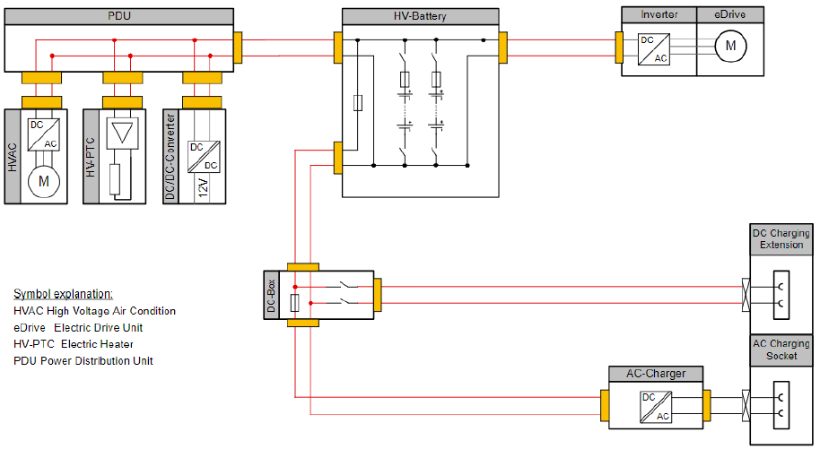
The aim of this supply chain is to integrate the 800 V powertrain delivered by SC1 and the 800 V battery system delivered by SC2 into the new Mercedes-Benz EQ demonstration vehicle. This vehicle will be provided by DAI with its series 400 V power net as a base. AVL will remove the complete propulsion system, consisting of inverter, motor, transmission and battery. The new 800 V battery will be integrated into the same compartment as the original 400 V battery. For the integration of the new 800 V powertrain, slight modifications of the original e-axel chassis subframe are necessary. Further, the electrical and thermal interconnections will be adapted according to the new electro-thermal system layout allowing a fast charging up to 350 kW in accordance to the new 800 V voltage level. The entire high voltage power net will be transformed from 400 V to 800 V, including all auxiliary high-voltage components like the HVAC heater, compressor and the DC/DC converter.
Based on the specification of the new powertrain and battery a vehicle simulation model will be used by AVL for the design of the thermal system, which will be assisted by data provided by HUT. Especially the high cooling demands during the battery fast charging will have a strong impact on the thermal system layout and the cooling component dimensions. New control functions for the powertrain and the thermal system components will be developed and integrated with the support of DAI. Further, OTH will develop and implement an energy efficient navigation. The navigation route is optimized to reach the fastest charging stations that are available and offer the lowest waiting time, thus reducing the overall travel time. The routing algorithm can be configured via a web application (e.g. on a computer or smartphone) or in the vehicle.
The highly efficient routing algorithm for electric vehicles will consider different requirements:
- Weighted routing graphs will be built in advance on the server to calculate the road network using OSRM. Contraction hierarchies will be applied to consider static data, both vehicle unspecific parameters (e.g. general speed profile, penalties, left-turning traffic, traffic lights) and EV specific information (e.g. terrain, traffic via time dependent graphs).
- The specific second routing graph will be built during the runtime. Based on the access to vehicle and infrastructure data, the calculation of best and most suitable charging stations (e.g. through Open Charge Map-Data and other data providers) will be done dependent on energy consumption and travel time to charging stations, available charging speed, reservation of the charging station (e.g. based on OCCP1 protocol) and the supplier of the electric energy.
- The routing will be adjusted to the battery profile and charging status to choose the best suited charging station to reach the destination within Europe. Different battery charging characteristics must be provided by the battery manufacturer and stored on the server, since the routing algorithm is highly dependent on the battery charging characteristics.
The communication system will rely on an LTE link from the vehicle to the hosting server, located at the OTH. The routing will be calculated on the server and the result will be transferred to the vehicle communication system. The result of the routing could either be displayed on a tablet or smart phone in the vehicle or forwarded, e.g. via Ethernet, to the on-board navigation system guiding the vehicle to its destination. The communication system is further able to transmit vehicle data, like speed, actual battery capacity from the vehicle to the server for further processing during the development phase. Data space and calculation capacity will be provided to the project partners. Together with the webserver and the mobile communication link, the energy efficient routing algorithm will be installed in the demonstration vehicle and evaluated in all three challenges (1000 km business trip, 2000 km family holiday trip as well as 4500 km Europe round trip).
Vehicle test drives will be performed to calibrate the powertrain and thermal management control parameters in the control units. Finally, the achieved performance shall be evaluated to validate the project targets with respect to functions and performance (i.e., test bench and real open road testing).
The powertrain integration will be based on the AVL development process and split in following phases:
Concept development: Based on the requirements defined in SC1 and SC2, the integration of the new components will be performed:
Geometrical modifications of the chassis subframe will be elaborated to fit the powertrain in the vehicle. A comprehensive electro-thermal vehicle model will be built up to design the cooling components.
- The electrical system layout changes will be defined, and components adapted
- Vehicle build up plan will be created
- Electro-thermal system functions will be defined, and vehicle implementation planned
- Vehicle test plan will be defined
Demonstrator build up phase: Based on the concept phase, the vehicle build-up will be planned and executed:
- Disassembling of the DAI base vehicle
- Geometrical changes for the integration of the powertrain
- Installation of the new 800 V powertrain
- Build-up of the 800 V power net
- Installation of the 800 V battery
- Implementation of the new electro-thermal control functions including the control units
- Installation of the measurement equipment to verify the electro-thermal energy flow
- Vehicle commissioning and first functional tests
- Vehicle road release
Vehicle test phase: After the road release, the testing activities according to the test plan from the concept phase will be performed:
- Chassis dynamometer tests
- On road powertrain and electro-thermal system control parameter calibration
During the last project phase DAI and AVL will show the potential of the new developed propulsion system during the three challenges:
Challenge 1: The 1000 km business trip
Two trips with approximately 1000 km each within 12 hours, including a maximum of 1.5 hours total charging time in not more than 3 stops
Challenge 2: The 2000 km family holiday trip
A trip from Stuttgart (Germany) to Bordeaux (France) and back shall show the potential for family holiday trips. The travelling time should not be more than 24 hours.
Challenge 3: The 4500 km project round trip
The final round trip will include all project partners and the funding authority in Brussels. Seven countries will be passed using the high-performance charging infrastructure across Europe. This last challenge is intended to be a high visibility marketing action, promoting the dissemination, exploitation and impact results of the 1000kmPLUS project.